¶ Spider X1S Troubleshooting
¶ Importing LightBurn configurations
Spider X1S LightBurn import file
You can download the Spider X1S LightBurn configuration file here.
¶ How to import files
1.Open LightBurn, click on "Devices" in the lower right corner to open the device settings interface.


2.Click "Import," select the machine configuration file, and double-click to open.


3.At this point, the Spider X1S device configuration has been imported into LightBurn.

4.After clicking OK, the pop-up window will close, and select "Spider X1S" in the lower right corner to complete the process.


¶ Additionally, you can manually configure the device.
You can click on the video link to watch it.
How to use LightBurn for image setup and some essential program settings.
(https://www.youtube.com/watch?v=8OTi8W8VwvA&list=PLSvZgUsDjmtb1d5tAs2laJT-r4hy2Sprw)
¶ How to adjust the working area of the machine using LightBurn?
User's question: In lightburn and Laser GRBL the size of my print area is 880mm x 880mm.Even when size is adjusted in lightburn it stays at 880mm x 880mm only have it set up at 400mmx400mm. Why is this happening?
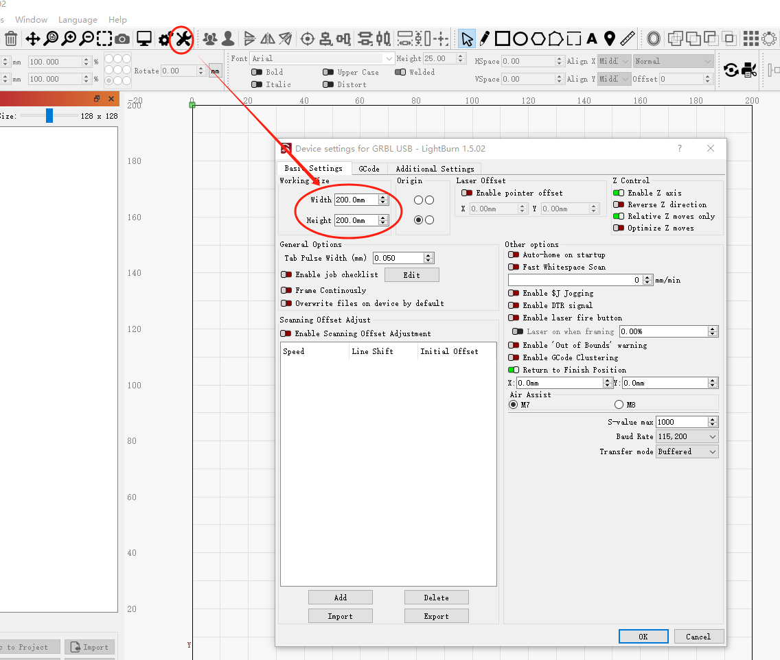
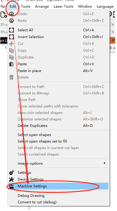
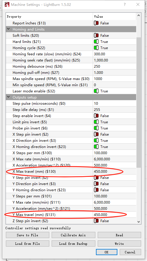
1. Enlarge the working area limit within the software.

2.Modify device settings for the working area.
Note: The working area setting on the device should generally be equal to or larger than the working area setting in the software.


How to determine the position of the X1S limit screw?
1. First, please check if there are limit screws and T-type nuts installed on the X-axis on the side of the reset direction. If they are missing, please contact us to arrange for replacement. The specific installation position can be found in point 3 below on how to adjust the position of the limit screws.

2. If they are present, please check the height of the laser head to see if it hits the side guide rail or timing pulley during the reset.

3.If so, adjust the position of the limit screws and T-type nuts as follows: when the limit screws contact the roller back plate, there should be a gap of about 3mm between the laser head housing and the guide rail (or side timing pulley).

4.If the machine still cannot stop during reset after starting up without installing the laser head but with limit screws, please contact us again.
¶ How to replace the X1S sensor wiring?
Open the side cover of the host with the screen to see the device motherboard. Unplug the terminals on the motherboard circled in the figure below and then plug them in again before testing.
¶ How to check the X1S X-axis reset problem?
1. Tighten the long screw for limiting the position a little more, and (with the laser head removed) manually hit the back plate against the screw repeatedly to knock off a little of the coating on the side of the back plate. (The reason is that the coating on the back plate may be too thick, which blocks the reset completion signal that should be transmitted from the screw to the back plate, and the coating needs to be removed a little bit manually).
2. Behind the laser head back plate, there is a small iron ring tightened with screws. Check whether it is tightened.
3. Open the side cover on the screen side, you can see the motherboard. There is also an iron ring tightened with screws in the lower left corner of the motherboard. Check whether it is tightened.