¶ Line Drawing Module
¶ Important reminder about Line Drawing Module
Neither the host nor the circuit board can be plugged in or out while the power is on, otherwise they will be damaged.
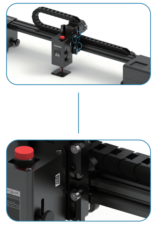
¶ How to install Line Drawing Module to the machine
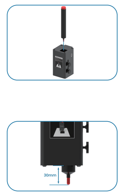
1. Insert the pen into the Line Drawing Module, please note the distance between the pen tip and the module is about 30mm.
2. Tighten the side screw by hand, place the 4.5-5 mm acrylic pad on the drawing surface.
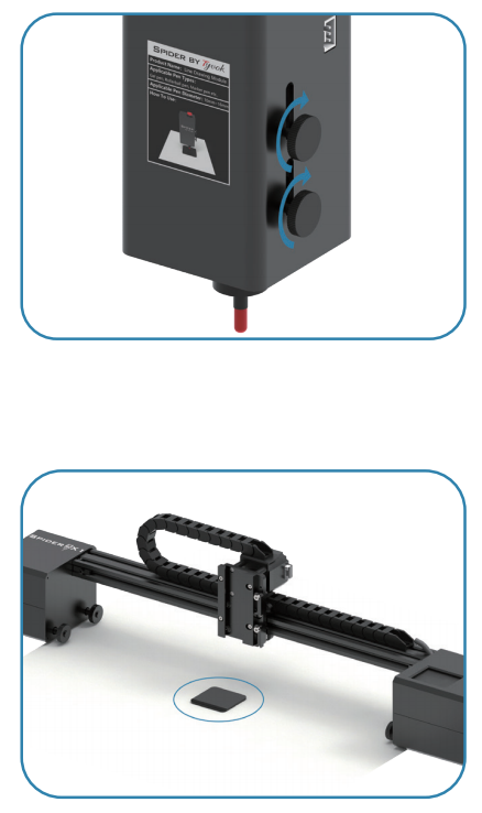
3. Insert the Line Drawing Module into the device guide rail, with the pen tip touching the acrylic pad, and tighten the quick release fixture firmly.
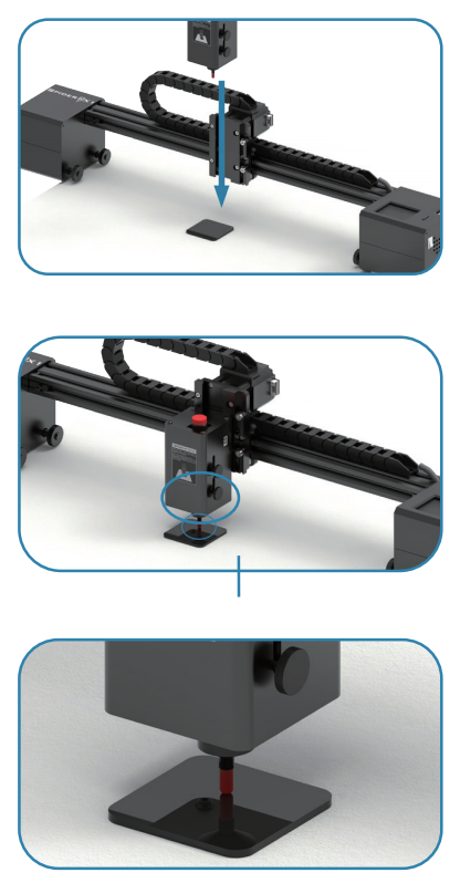
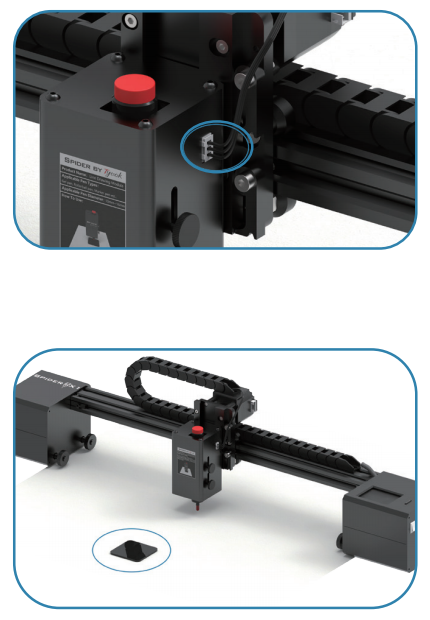
4. Connect the 3-pin terminal to the Line Drawing Module, remove the acrylic pad, and you can start working.
Software Settings: The Line Drawing Module is compatible with laser engraving software. The power setting must be set to 100%, and the speed should be below 1000mm/min.
¶ Line drawing module——LightBurn
In LightBurn, the processing speed must be set to 1000mm/min or below, with a processing power of 100%.

Before you start engraving, first determine what kind of drawing you want to create using the line drawing module. This can be divided into two situations:
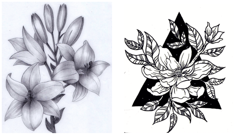
1. Line drawings, as shown in the image below. You need to use vector graphics as the source file or convert an image to a line drawing in LightBurn.
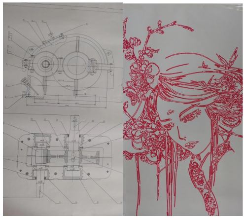
(Left image is a vector source file, right image is an image converted to a line drawing)
If you are using vector graphics, simply import them into LightBurn, set the size, mode to “Line,” and adjust the speed and power. You can then start working.
If you are using regular images (such as jpg, png, etc.), you can convert them to line drawings following these steps:
(1)Right-click on the image, select “Trace Image,” and a window like the one below will pop up.
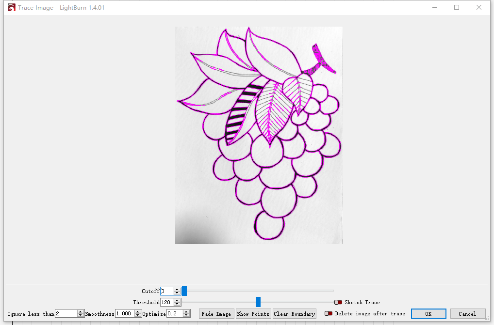
(2)Adjust “Cutoff” and “Threshold” as needed, click “OK,” and then delete the image layer.

(3)Adjust the processing position, size, speed, and power, right-click “Preview” for a preview, and start working once you confirm the effect.
2. Directly processing the original image, as shown below. The left image will represent the brightness of the original image using point density during processing, while the right image will only have two colors, black and white, and can be filled with lines.

You can directly use regular images (jpg, png, etc.) for processing, preferably high-definition images for the best results.
If you want to create works with brightness and contrast(as in the left image), you can follow these steps:
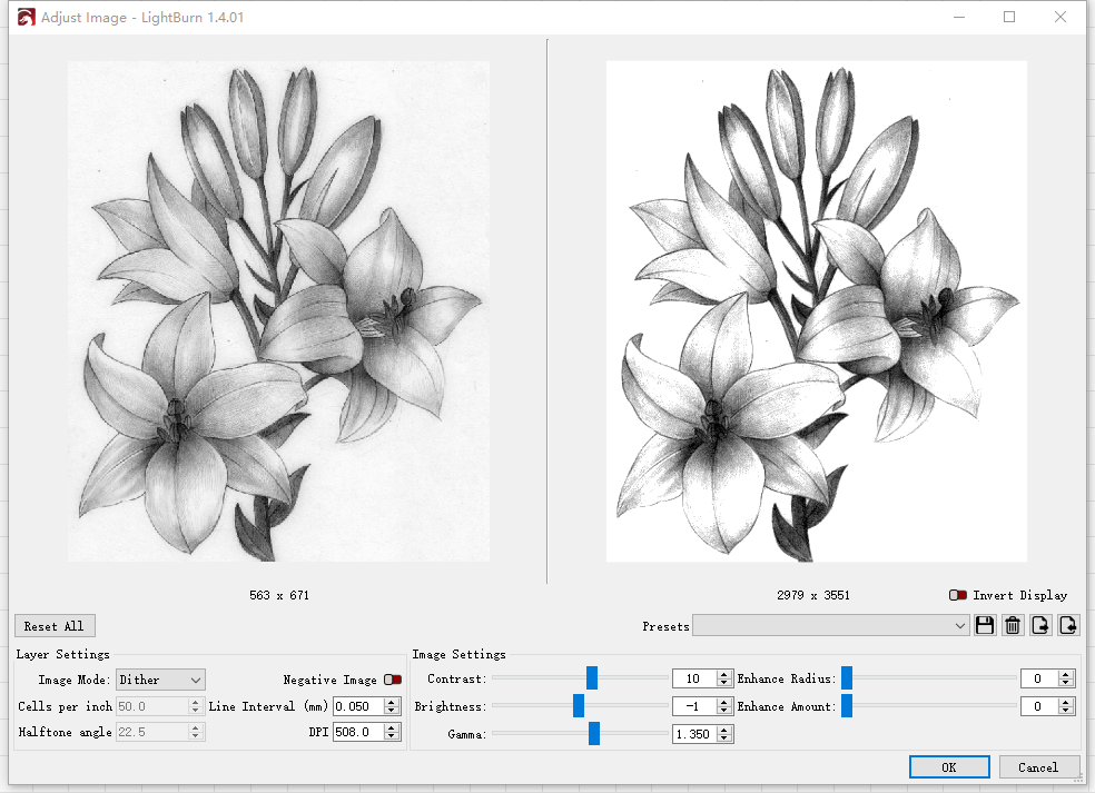
(1) If you are using a non-white background image, you need to convert it to a white background image, following these steps (if using a pure white background image, you can skip tostep3). Right-click on the image, select “Adjust Image,” and a window like the one below will pop up.
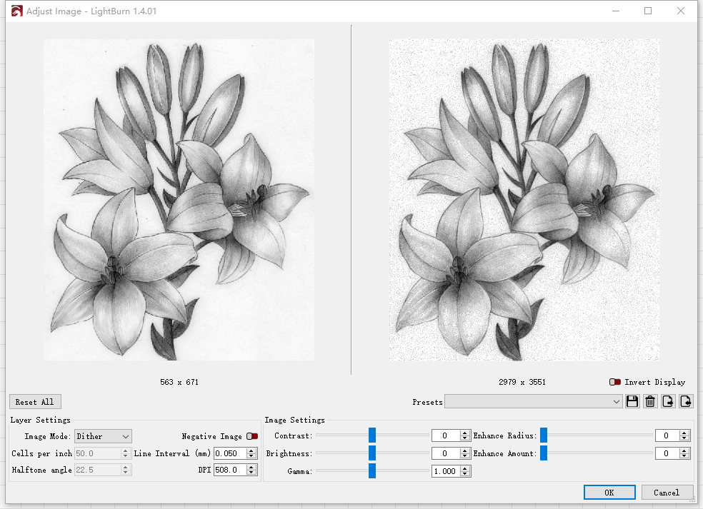

(2) Adjust “Contrast,” “Brightness,” and “Gamma” parameters as needed, making the image background tend towards white while ensuring that the main subject is not overexposed. Click “OK” when finished.

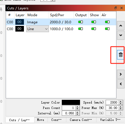
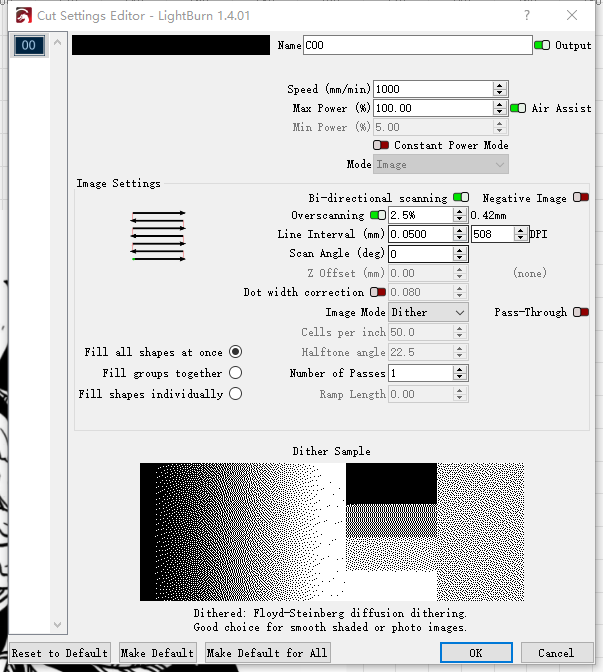
(3) Double-click on the “Image” layer on the right, and a window like the one below will pop up. Make sure “Image Mode” is set to “Dither.”
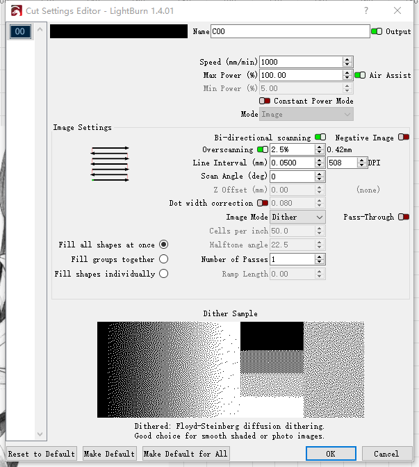

(4) “Line Interval” is adjustable and determines the level of detail in the processing image. A smaller value provides more precision but increases processing time. You can adjust it according to your desired effect.
(5) Adjust the processing position, size, speed, and power, right-click “Preview” for a preview, and start working once you confirm the effect.
If you want to create works with no brightness and contrast(as in the right image), only black and white, (recommended for processing on harder surfaces, as processing on paper may tear it), please follow these steps:
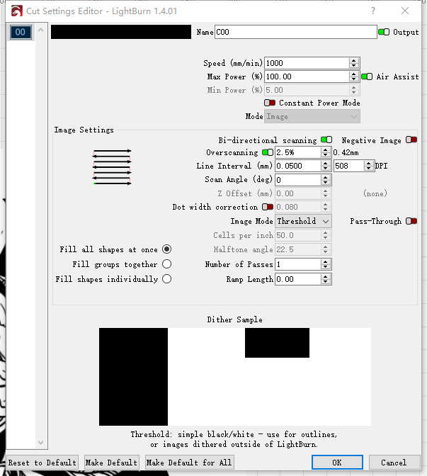
(1)As mentioned earlier, convert non-white background images to white background images, no repetition is required. After importing the white background image, double-click on the “Image” layer on the right, and a window like the one below will pop up.

(2)Change “Image Model” to “Threshold,” then adjust “Line Interval” as needed, and click “OK.”

(3)Adjust the processing position, size, speed, and power, right-click “Preview” for a preview, and start working once you confirm the effect.”
¶ When using the brush module for line drawing (line drawing)
You need to make some special settings for LB.
Double-click the layer in Line mode.
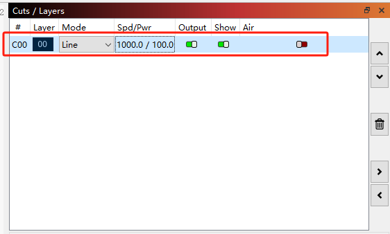
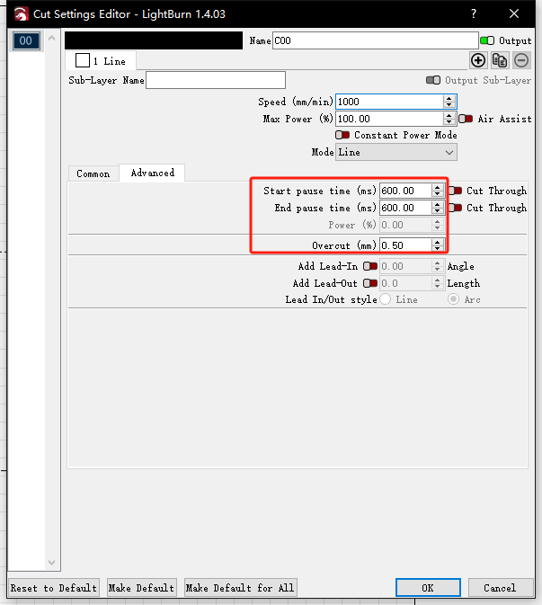
Click Advanced.
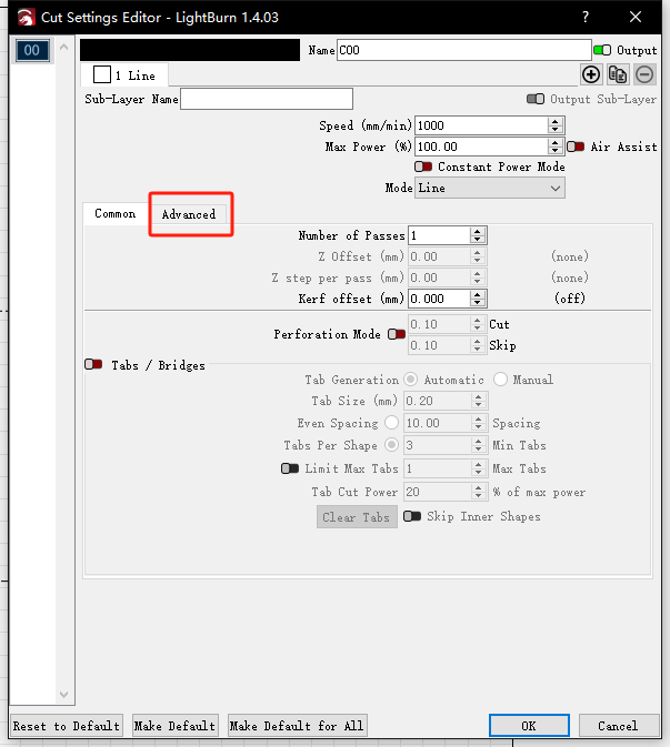
Just change the values below as shown in the picture. If you switch back to the laser head module, you need to change this value back to the original value. (emphasis added)
¶ Line Drawing Module Screw Tighten
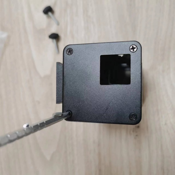
1.Unscrew the screws on the side manually.
2.Remove the screws on the back slider using an Allen wrench.
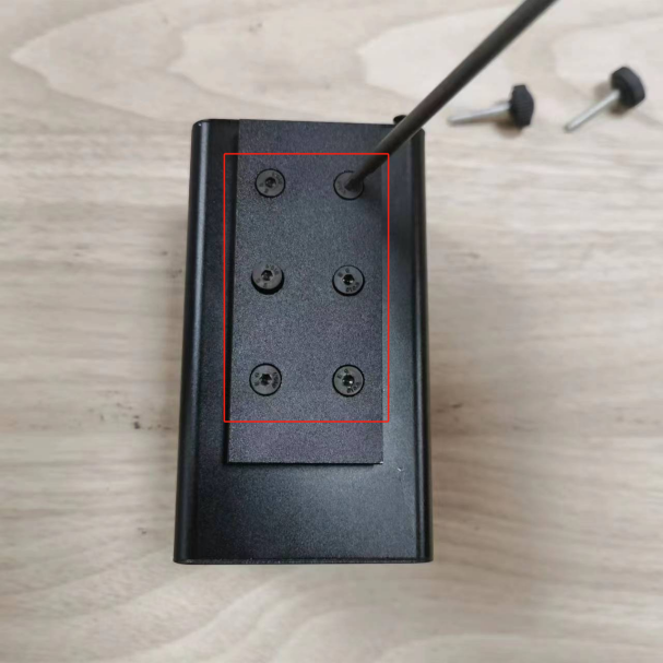
3.Take off the top cover screws of the line drawing module with a Phillips screwdriver.
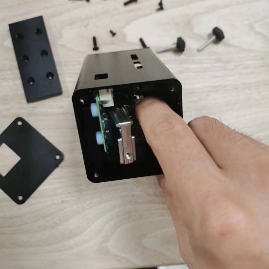
4.Remove the internal components.
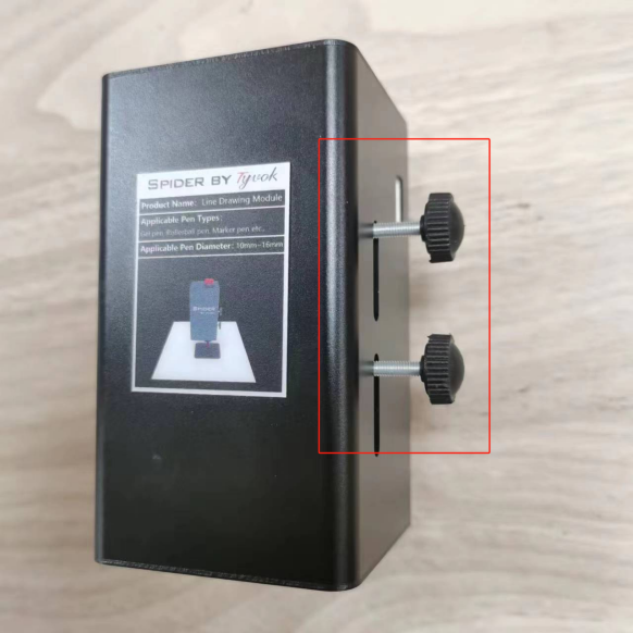
5.Place the tilted angle iron (red border) back onto the top of the blue border part.
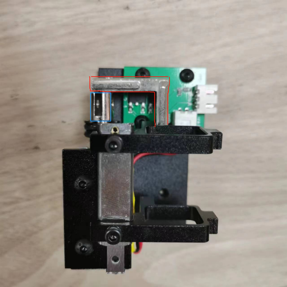
6.Tighten the screws on the side of the angle iron.
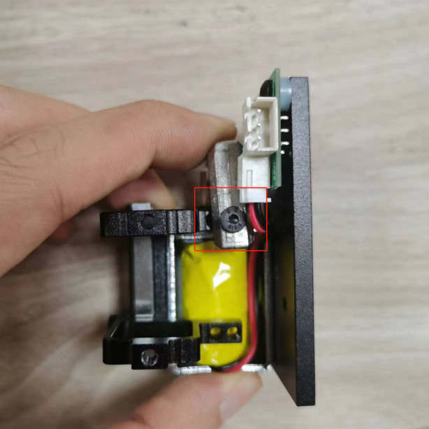
7. Reassemble the other components in their original positions.